Voltage Drop Calculator
A quick tutorial
But why???
Go RIGHT → for the tutorial on using the tool.
Go DOWN ↓ to find out why you might use the tool.
If you want to know why I made this go to the last slide.
If you want to get started, go straight to the tool.
Long cables have voltage drop
When you supply power to something (a light, a computer, whatever), you do so by sending electricity along a cable.
Normally, in most low voltage situations you can more or less ignore the voltage drop over the cable. This is because:
- it is usually negligble (unless you have very high current draw); AND
- you have a power source/point per item you are powering (i.e. you are not daisy-chaining).
Power outlets are scarce underground
In tunnels or underground mines, you might want to install cameras or Wi-Fi to cover large areas underground. However, you have to run power to your devices - sometimes over a long distance.
An example underground mine
For example, an underground might might look like this:
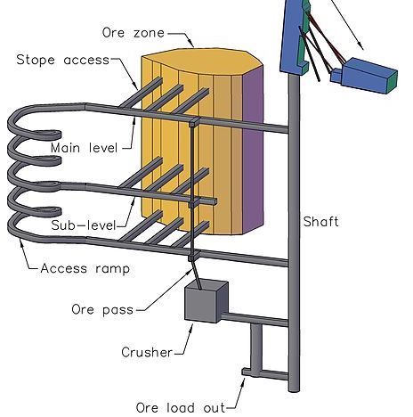
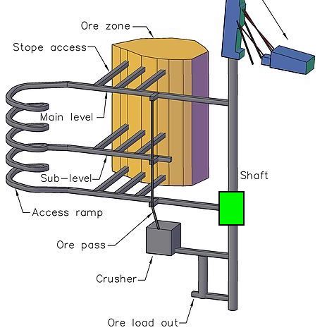


- There is power available near the shaft.
- We need to install cameras in these 2 places.
- We might need to run power from the shaft.
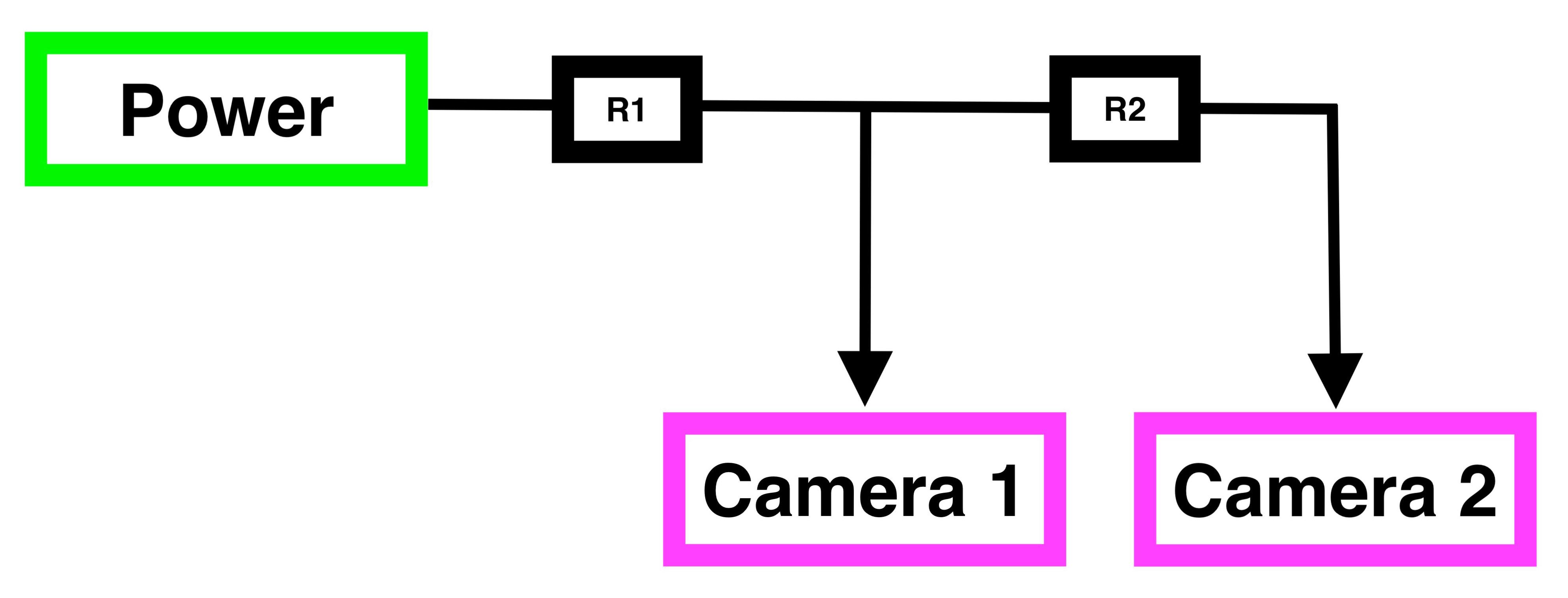
- Which leads to a circuit something like this:
(where R1 and R2 are the resistances of the long cables)
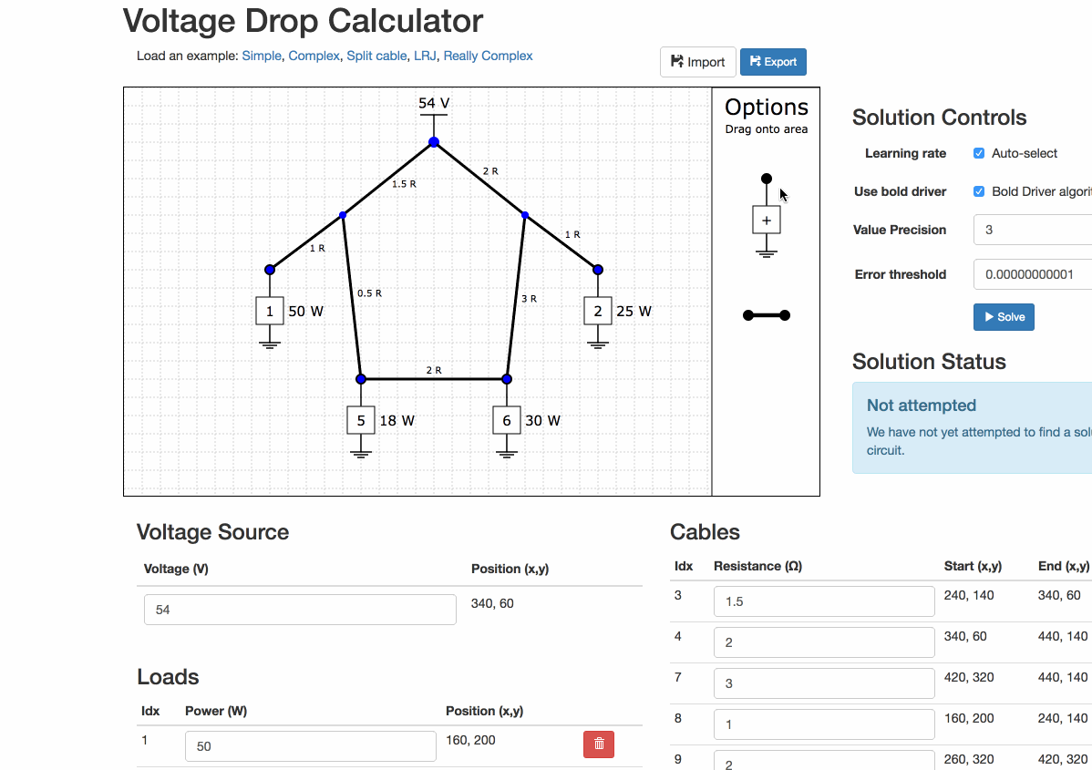
Working through the circuit
We can convert it to a circuit diagram
We have assumed here that the long cables have a resistance of 2 ohms each with no complex components. You need to approximate this value yourself, but it is usually the length in metres multiplied by the resistance per metre.

If the cameras behave like resistive loads
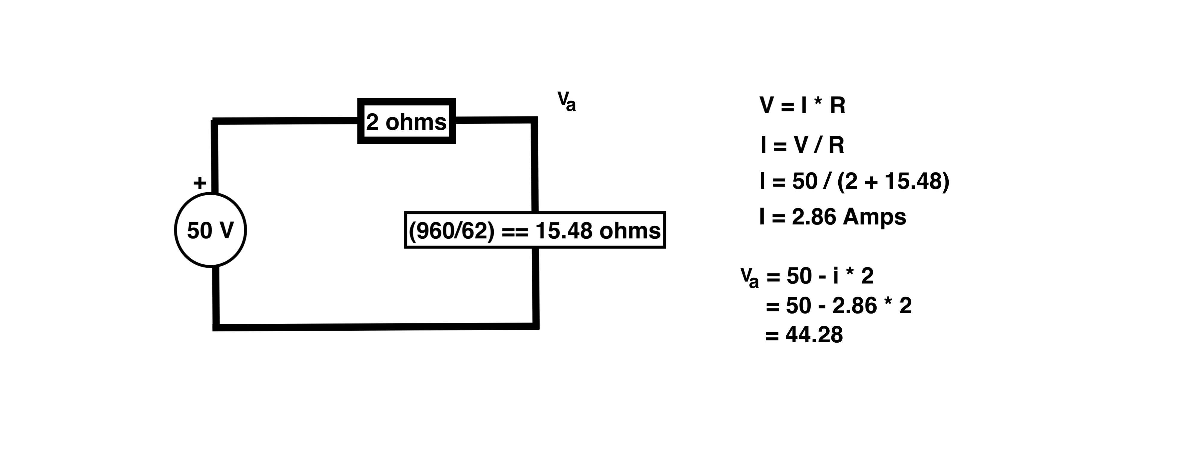
Well then we could model them each as a 30 ohm resistance, and then we could analyse this like any simple circuits problem.
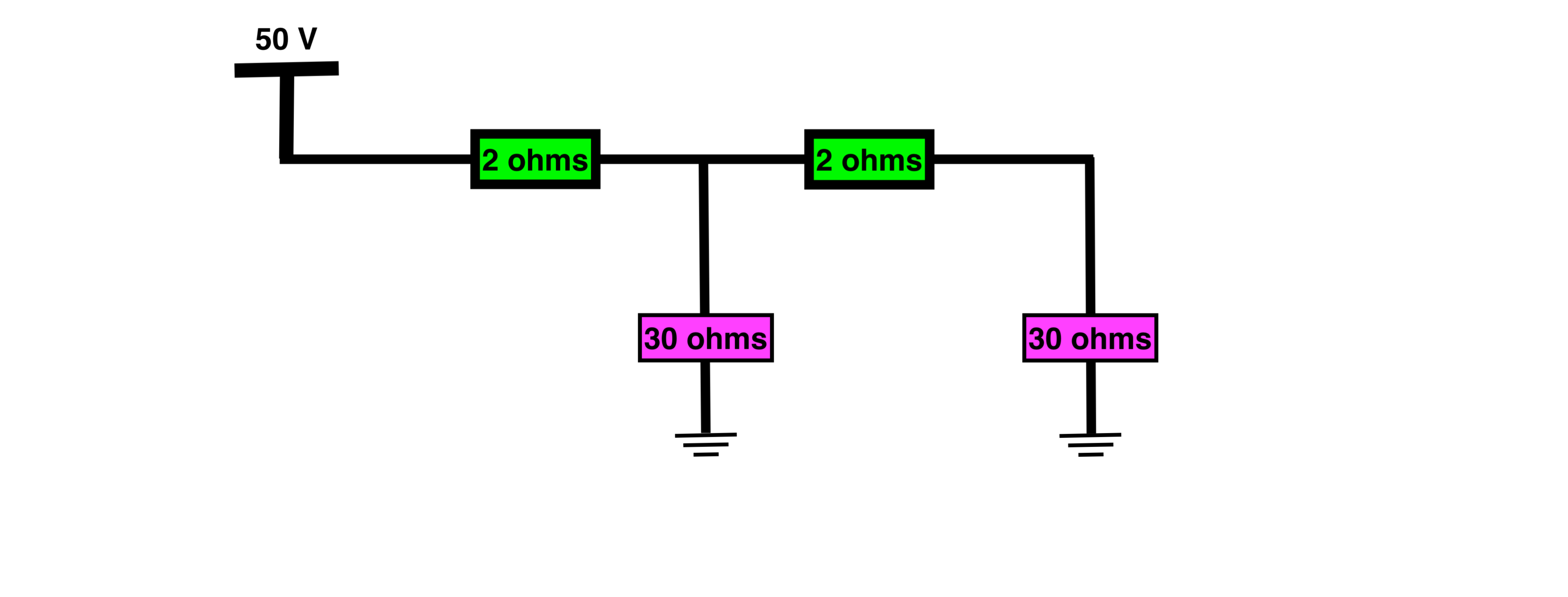
We would add series resistances together
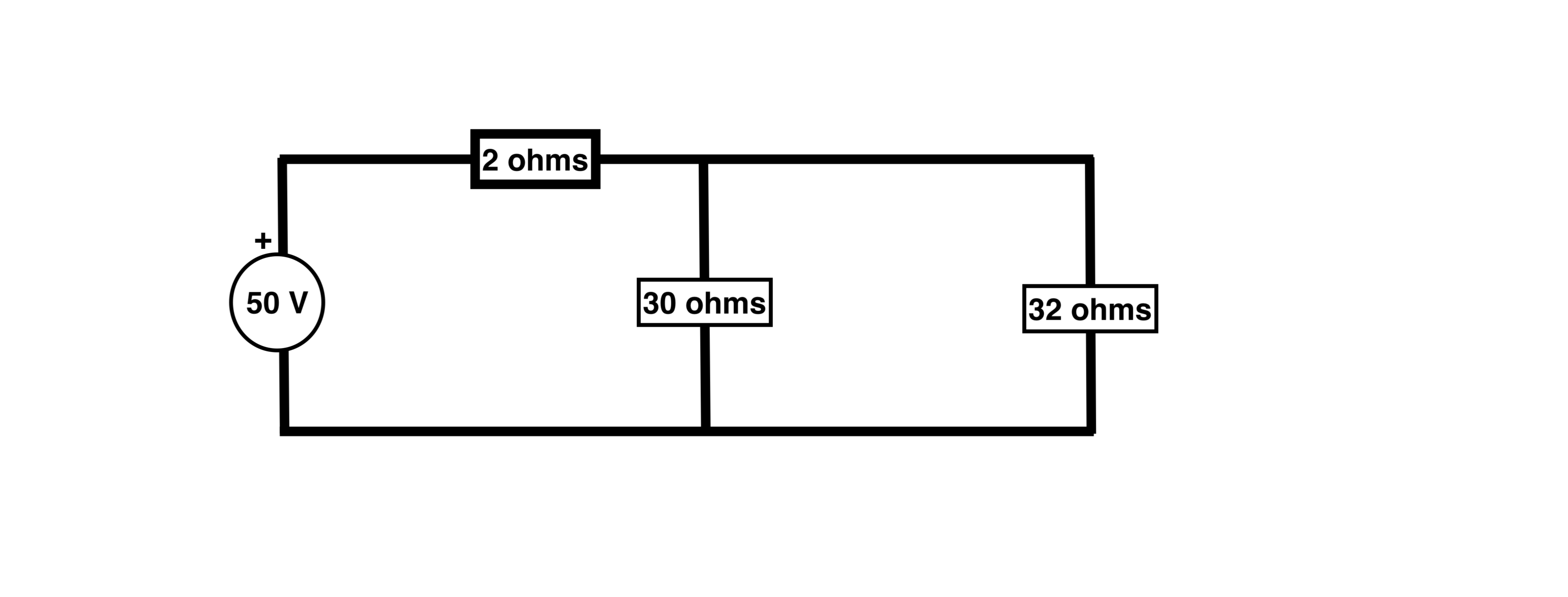
We would combine parallel resistances and then perform the basic circuit analysis. Easy!
But cameras are not resistive loads
Digital devices typically need a stable DC voltage to operate. This is why your laptop, phone, security cameras etc all come with a "power pack".
The power pack does the job of cleaning and regulating the power for the device.
This is a deep and complex topic, but there are power circuits that can convert from AC to DC, from DC to DC, from higher to lower voltages and from lower to higher voltages.
Cameras are constant-power loads
You might have a camera that:
- accepts between 12-48 V DC, and
- draws 10 Watts.
The camera is a 'constant-power' load, i.e. it modulates the current it draws based on the voltage it is receiving so that it always consumes a constant power.
Assume the camera's optimal voltage is 24 V and that the regulator in the camera is 100% efficient (P = I * V).
If you supply:
- 24 V
-
The voltage is exactly what the camera needs.
So P = 10 and V = 24, then I = 0.42 amps - 48 V
-
The regulator steps the voltage down, "gaining" current in the process.
So p = 10 and V = 48, then I = 0.21 amps - 12 V
-
The regulator steps the voltage up, "drawing" more current to achieve this.
So p = 10 and V = 12, then I = 0.83 amps
Using the camera voltage (Vc) and current (Ic), we can see how this non-linear behaviour affects the voltage we need to supply.


- With a basic circuit like this →
- The supply voltage is calculated like this →
- 24 Vc requires 24.84 V in supply
- 12 Vc requires 13.66 V in supply
- 48 Vc requires 48.42 V in supply
The camera can be modelled in a number of ways. For example, you could consider the camera as a resistive load that changes resistance based on the available voltage.
Using the numbers from before, if you supply:
- 24 V
-
The current is 0.42 amps, and 24V drop across the camera.
So the equivalent resistance is R = V / I = 57.1 ohms. - 48 V
-
The current is 0.21 amps, and 48V drop across the camera.
So the equivalent resistance is R = V / I = 228.6 ohms. - 12 V
-
The current is 0.83 amps, and 12V drop across the camera.
So the equivalent resistance is R = V / I = 14.5 ohms.
But wait! That wasn't hard!
You are right, doing it for one device is not hard, and doing it for two is manageable, but doing it for 3+ take a serious amount of time.
This is because the voltages throughout the circuit affect the current / voltage and thus effective resistances throughout the circuit which continue to affect....you see the point.
I don't believe you
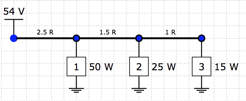
That's ok, just try solving this one by hand
(answer on the next slide)
Ok, so here is the same circuit with the solution.
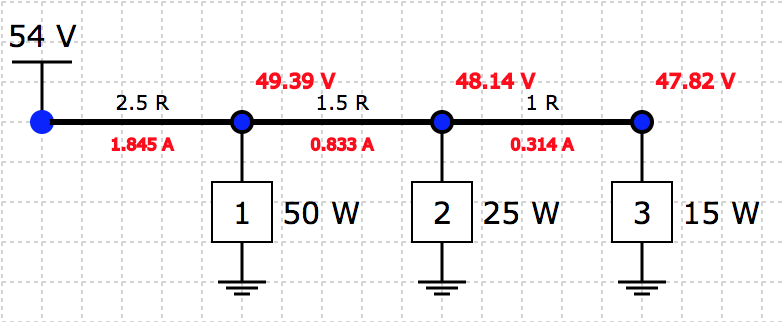
Fortunately it is easy to check the solution once you have found one.
Right, so I guess I use the tool
Yep, the tool solves these problems by starting with initial conditions for the 'effective' resistances and iteratively moves them up and down to reduce the error in the answer.
Hopefully it eventually arrives at some numbers that reduce the error to a small number, and thus represent a "solution" to the circuit (within some tolerance).
However, some circuits are unsolvable!
Unsolvable circuits! Huh?
It can seem counterintuitive that a circuit like this could not have a solution.
It occurs when the current flowing down the cable would cause the voltage to drop too much to be able to supply the power required.
Try the simple circuit from before with 50V input, 50W load and 12.5 ohm cable resistance. This is the limit of this circuit, any higher cable resistance and the circuit will not solve
In real life this also does occur, but tends to follow this pattern:
- Circuit receives power, switch-mode power supplies (SPMSs) start to draw power
- Current increases, which lowers the voltage for the SMPSs
- Voltage drops low enough for SMPSs to stop working, they turn off
- Current decreases due to SMPSs turning off, voltage starts to rise, so the SMPSs turn on again
- Whole circuit flickers on/off as this cycle continues
What next
Learn the tool →!
How to use the tool
The following few pages will step through the process of using the tool.
We will cover:
- Modelling your situation
- Solving the network
- Other stuff!
Modelling your situation
Determine your nodes and branches (i.e. elements and cables)x Any point where the power splits in different directions is a branch. This could be where it splits to head in multiple other cables, OR it could be where the power is tapped off into a 'power element'.
Calculate the resistance of each cable It will hopefully be as easy as multiplying the length of the cable by the manufacturer's specification for the resistivity per metre. It is usually not work modelling short cables, like the ones you use to connect the nodes.
Calculate the power of each load There is a bit of art here, but it is usually doable. For example, if you have two 15W cameras and a 10W Wi-Fi access point at a single location, you might say the total load is 15 + 15 + 10 = 35W. You could also build in some buffer here if you like.
Make a drawing of the network schematically This will make placing the items on the diagram more straight-forward
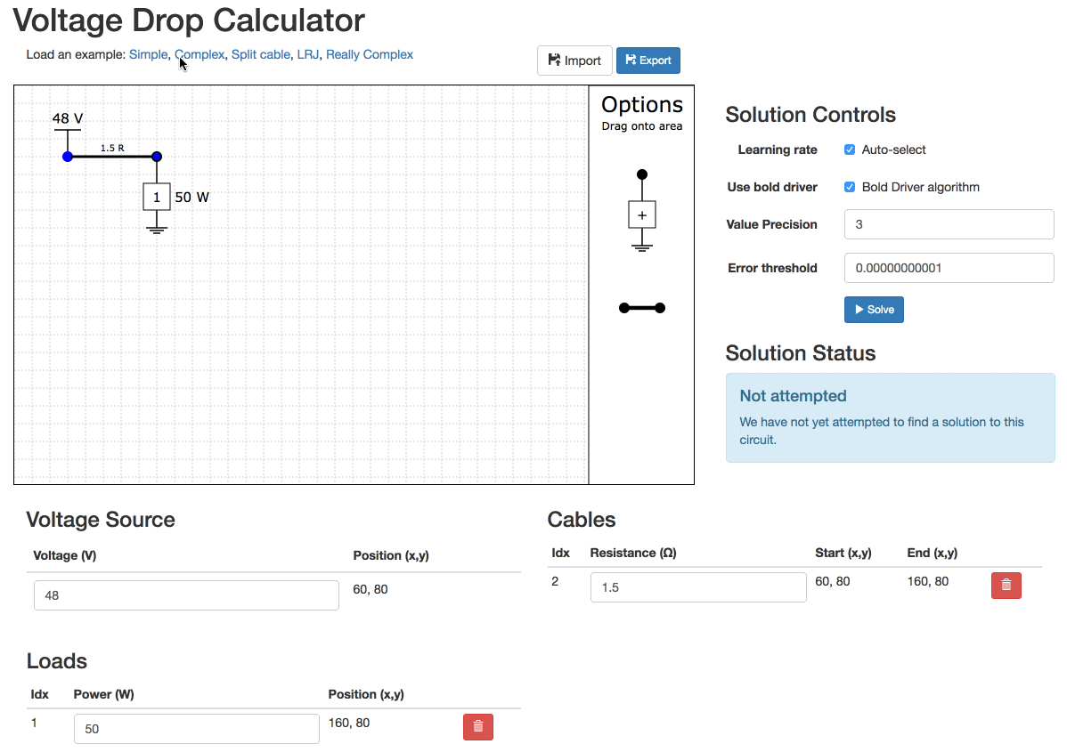
Build the network in the tool
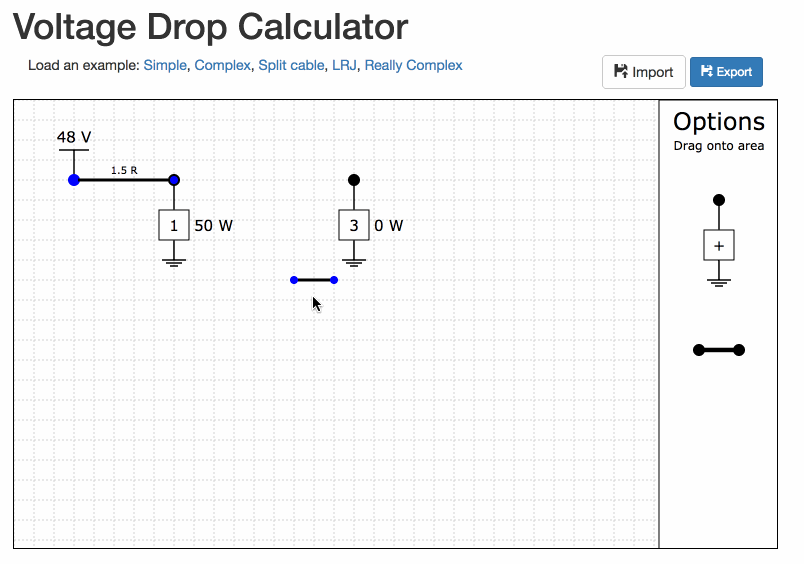
Drag the loads and cables from the 'Options' area onto the grid lines.
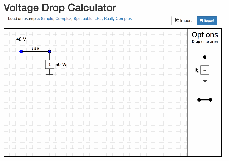
Build the network in the tool
Move the voltage source and the loads by clicking and dragging them.
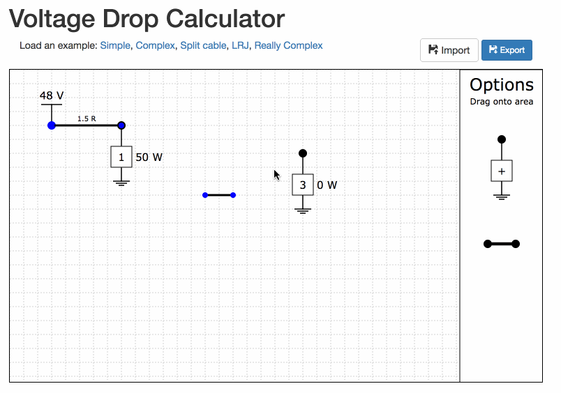
Build the network in the tool
Move the cables by first click them (they should become highlighted, and then dragging either end.
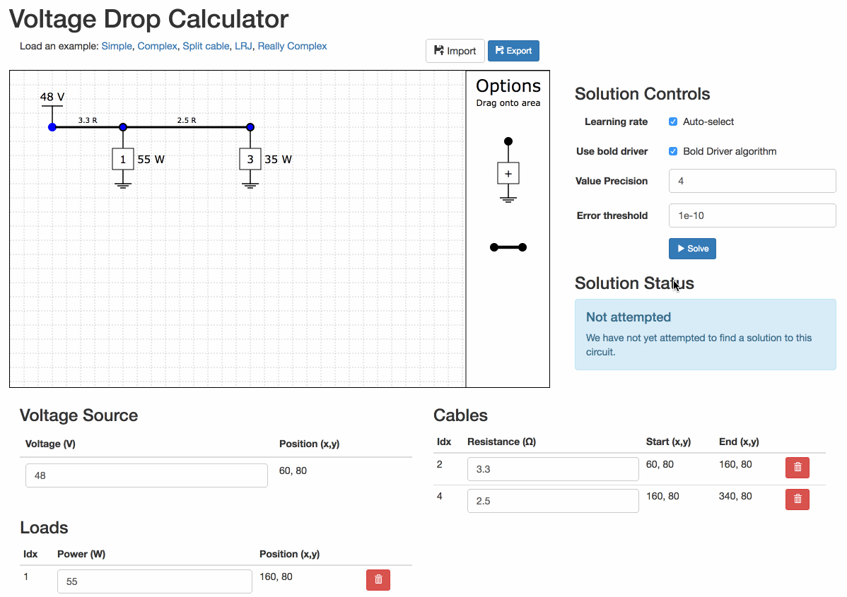
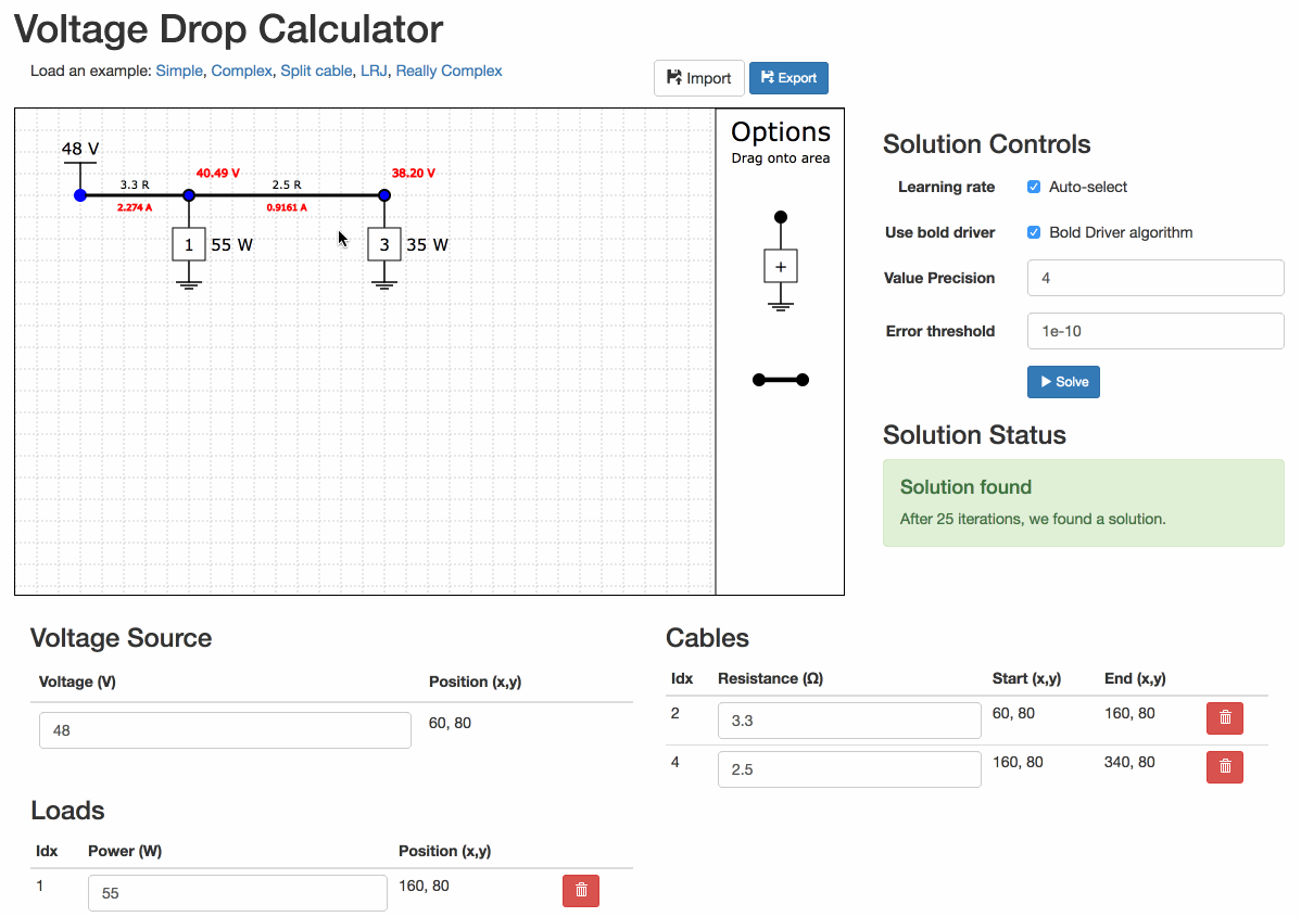
Fill in the values
For example, I have two loads, one 55 W and one 35 W arranges along a single cable. The first section of cable is 330m, and the second section is 250m. If my cable has resistivity of 0.01 ohm / m, the resistances are 3.3 ohms and 2.5 ohms respectively.
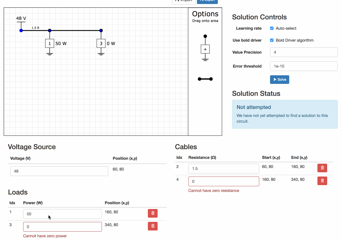
Find the solution
Click on the "Solve" button to attempt to find a solution.
Play with the precision
You can change the precision of the numbers on the diagram.
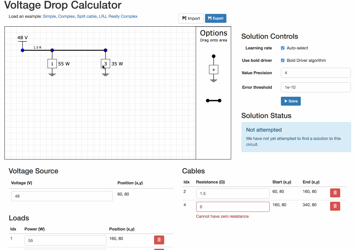
If you have errors
Errors with the circuit will prevent the solver from running.
Built in examples
There are some built-in examples of varying complexity.
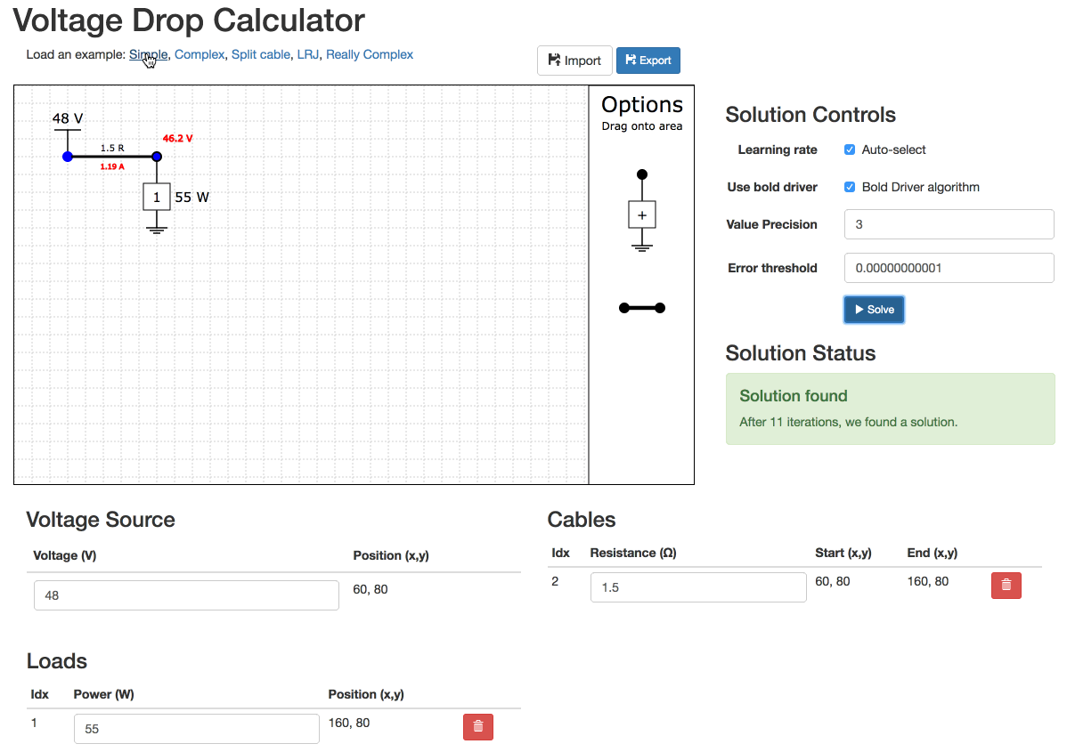
Unsolvable Example
Sometimes networks are unsolvable. You have to experiment to have them solve.

Unsolvable Example
Even really simple networks can be unsolvable!
Save for later
You can export your design and import again later. You can even edit the file as JSON (because that is all it is)
That's all
You are now fully aware of how to use the tool.
Take me to the tool now!
Thanks for making it this far, I hope you find a use for the tool. Some other things to know:
Why did I make this
I made this for a number of reasons.
- I had taken some of the machine learning course on coursera, and had an inkling that the gradient descent technique might be a good way to solve these long-line voltage issues.
- I was working with some great guys at Mopani Copper Mines who were installing long-line networks and wanted to know how much equipment they could hang off the ends (without spending weeks doing the calcs or over-specifying dramatically).
- I had a bit of spare time and once I got a version to solve a basic circuit, I thought it would be a great tool to put online